Direct drive setup for machining. Any thoughts ?

MkngStffAwesome

Active member
TD05 housing
TP 4070CM

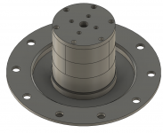
Direct drive setup

Designed to be machined from 20mm aluminum


1636930197080.png

In the first pic you can see a section that is removable to to allow access to the coupler
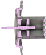
1636930241063.png


Bearings are 9x17x5mm Ceramic (not sown)
There is an allowance for 1mm of play in and out.. The idea is i'll shim that out to be the correct distance between the housing and the compressor wheel


The total height is 62mm from the back of the housing (shown here) to where the motor mounts .. that means the motor sticks out about 170mm. With the current mounting location this should be ok.


Thoughts.
 
That should work fine. Are you reusing the original turbo's shaft? If not, the most reliable way to go would be to drill/tap the actual impeller shaft to accept the motor shaft directly. But a coupler would work too. As long as the tolerances are good, alignment shouldn't be a problem. Though my hex drive setup works well and allows for some misalignment (though I doubt I have much more than a thousandth, if any); I'm starting to think I over-thought the bearing requirements. In our applications, the bearings have very little stress. As you probably know (I assume you looked into available bearings); small bearings are much easier to find with our rpm requirements. Of course, aside from cost, going over the top with bearings is better than going cheap, just food for thought. My dual angular bearing setup is massive overkill. But it's what the Vortech came with. If I was to do this again with a Vortech, I'd use bearings with a smaller OD and machine spacers to fit.
 
Look a lot like my set up but mine is a little bit more compact. Remember how tall the turbo can be at the end. The idea of the coupler is a good idea with your set up but the down side is more lenght. The shaft can be machine in 1 set up so it will be perfectly straight. For the coupler, custom ones can be the way to go to be sure its all perfect. The thing I dont like for the coupler is the screw we use. The shaft can be easaly unbalence.
 
One thing I think of. We know MGM is pumpt about our projects. MAYBE we can use custom shaft with there motors to fit our turbos? After this, we dont need a super fency complicated set up?
 
yeah i know what you mean about the couplers which is why i didn't want to do it this way..

Every method has some downfall. I think about the problems with belts or gears and they have their problems also...

If this doesn't work i figure i can just get my own couplers made up something like Alex did. i actually really liked that idea.
 
sorry i forgot to answer your question.. that is a new machined shaft... the wheel says it's 6.48mm so i guess i should make the shaft the same 6.48... for the bearings it says 9mm ID so should the shaft me 8.99 or something ?
 
You need to check the allowance And tolerance for a 9mm shaft bearing. I don't know the right size, I use to make it with the bearing on hand avec test it while machining.
 
Maybe a nice fit with the couplers and the shafts with male and female groove to get the perfect alligment. Using only screws and no nuts
 
If you're worried about shaft imbalance, you can mill a flat on the outside of the coupler opposite where the setscrews are. The smaller diameter you can keep your coupler down to, the less imbalance it'll have. I wonder if the motor manufacturers take shaft flats into account when balancing them.
 
i dont use set screw couplers.. they by design force the couplers/shaft to the opposite side of the coupler and thus out of center and balance.. i much preferer the camping ones which ensures center alignment. Clamping ones also dont require a flat spot...

i have a you tube video on how bad set screw couplers are.... in saying that if the coupler and shaft are bang on size wise then this is minimal ... In general buying high quality ones are more important.
 
I think if we made custom coupler, they can be perfectly centered. If we made the coupler with tight fit you can use loctite to fuse it to the shaft or we can make a heat fit. The problem with heat fit it can be extremely hard to get the right fit with tiny mesure. Using one or the other you don't need set screw to secured them on the shafts. To be sure that each coupler is center to the other, like I said, we can make s groove on each face of the couple (one male and one female) so they will be centered. Then, one of the coupler can be threaded to use only screw.
 
For my current hex drive coupler, I used an 8mm reamer to hit the mark (8mm shaft). There's less than .001" play between the motor shaft and the coupler. I'll likely have to make another one for LMT motor (10 mm shaft); this time I might buy a slightly undersized reamer but they're hard to find. Maybe I'll use a small boring bar to get the perfect fit.
 
I can give you some tricks and tip! Even if you machine the diameter and drill the hole ine the same set up, the hole can be precis but it's almost impossible to be concentric with the outside diameter. The only way is to use a boring bar. BUT a boring bar for a hole of 10mm good luck haha it will be a pain in the ass to have this precis. So my tricks here, mount a 9mm endmill on your tool holder, then, use it like a boring bar. It will be way more rigide! Drill your 9mm hole then use your 9mm endmill like a boring bar.
BUT there's an other way that I would use if im macking your set up. Endmill don't flex and drill flex. So this is why I would'nt use drill and reamer to make a concentric hole. Since 10mm is .393" and 3/8 is .3875 use a 3/8 endmill like a reamer! Drill your hole juste couple touzen down and drill the rest with the endmill. If you chuck on the lathe is pretty much center, you will get a hole VERRRYY clost to 10mm and 100% concentric. If you are lucky you will get between .389-.393 if the hole too tight, heat it a little bit and blablabla you probably know how this work.
Hopfully you will understand if not just tell me 😁
 
I've been thinking about how to do it. I did think about using a 3/8" endmill and then a small boring bar - I'm still thinking how to actually make it. I've even considered buying a reground 10mm endmill - that should be ever so slightly under size. I have two chucks for my lathe - a 3 jaw scroll which has about .003" runout, and then for precise work where I'm not making all the machined surfaces a 4 jaw independent. Ideally I wouldn't have an interference fit, but a near-perfect fit.

I've also considered making a slug that slides on the motor shaft nearly perfectly, and press-fitting in the socket end.

But I don't want to get MkgStffAesome's thread off track. I've got a little bit of time to think this through.
 
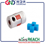
Fyi i have bought one of these from this company.. previous coupler testing has shown these to be machined well.. (not cheaply thrown together)

1637024240168.png

In a perfect world this is balanced. lol
 
Yeah look i know what you mean... But i feel like we just have to try some things and see if they work or not... We are all pioneering here.

If this doesn't then i guess i'll have to get something made up... But i do want it removable, so i dont think press fit or heating stuff up would be something i would be interested in.
 
That coupler design has been used in industry for at least 50 years. It does work pretty well - I remember playing with one when I was like 10. I'm not sure how it would do at elevated RPM but I think it's worth looking into. I'm worried it would be a bit unbalanced if the rubber section is allowed any a slop.
 
Top