BMS & Chargers

MkngStffAwesome

Active member
Firstly i dont claim to be an expert on these subjects, this is just a brain dump of what i have learnt in relation to BMS and chargers for our application.

BMS
Firstly we need to understand that "BMS" does not mean a "Charger". A charger is typically an independent device to the "BMS"

1627853991101.png


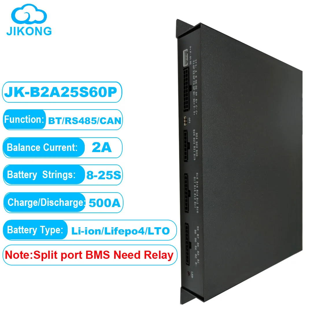
Typically the Job of a BMS is to monitor the voltage of a complete pack of cells and ensure that no individual cell goes out of the predefined range.. If the voltage of a cell goes to high due to charging or to low due to discharging then the battery will be disconnected from the Motor or Charger to prevent catastrophic damage to the battery. In this example below these thresholds are customizable.

1627854414010.png

As part of the "BMS" it's typical for it to "Balance" the pack of cells. It will detect a variance in individual voltages between the cells and try to equal them all out so all the cells are the same voltage.. This is typically done via a resistive load added to the cells displaying higher voltages like the one below, but it can also be done with an "Active" balance that takes some change from the higher voltage cells and gives it to the lower voltage cells.. This is far less wasteful than a resistive Balancer.

It's important to add that you can get Balancers independent of a more complex BMS.
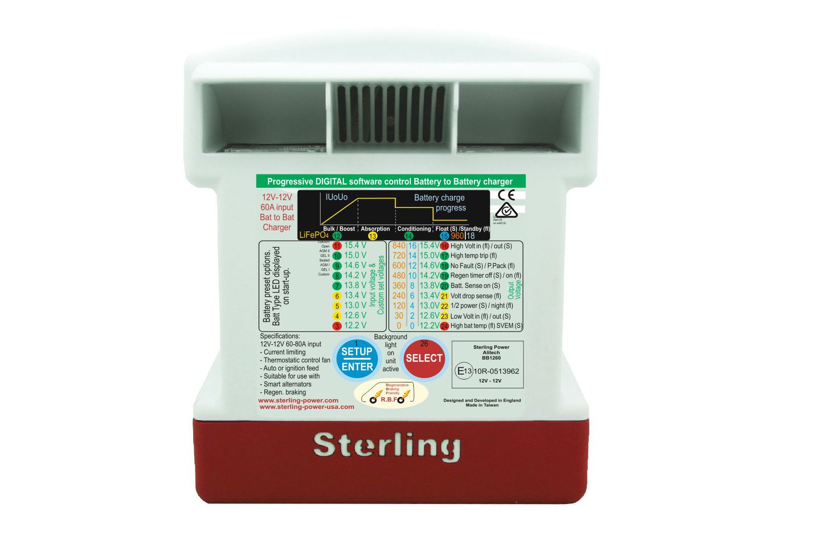
Some chargers have balancers as part of the chargers. This is the case when it's not expected for there to be a BMS in place.. Like in RC applications.

1627855015458.png

Do i need a BMS, Balancer for my E-turbo setup.

In theory you do not need a BMS because in a perfect world the battery will be perfectly balanced from the factory and you'll never over charge or over discharge the battery. However we do not live in such a world so a BMS is a good idea to prevent damage to your batteries by accident.

If you don't have a BMS in place during charging and discharging you'll have no way to know if the individual cells are out of voltage and there will be nothing in place to save your batteries, So yeah you need one. However as long as you have a high current Balancer in place and you use some other voltage monitoring system to prevent total Pack over charge or discharge then you should be "OK". This strategy normally also includes intentional under charging and under discharging to give the pack some room for different individual cell voltages despite the balancer being in place.. This is the case because most Balancers will be UNable to move enough current around when the battery is being charger or discharged at higher rates than the balancer can achieve.
 
Last edited:
Chargers
For this section we are going to assume that we are talking about charging from the cars alternator and that there is a BMS in place performing the Balancing.

To my surprise i have been unable to find an off the shelf charger to suit my needs of changing from 12v to 12s that can be remotely turned on and off. So it seems we'll need to make something.

To fully charge a lipo you need two basic modes Constant Current (CC) followed by Constant Voltage (CV) So we'll need a means to achieve those two things.

1627863940443.png

To start with we'll need something that can boost the voltage from 12v to 50.4 (12s lipo) and then something that can limit current.

Something like this should be able to do both.
1627864314588.png

Please note that despite the add saying 1500watts it's actually 30amps of input power so at 12v it's only 360 watts. 360 watts doesn't sound like a lot and it's not but at the same time 30amps could be a alot of extra current when adding that load to the alternator. It will just depend on how much extra current your alternator is able to deliver if at all.

Sadly just the above alone is not enough to charge your batteries correctly you'll also need to add a controller like an Arduino, a current sensor and a mosfet. This can then monitor the current and turn the charging off wen current falls to the correct level. Also you can use this to turn the charging function off then you'll "Boosting". The controller doesn't actually need to know the battery voltage but i'd add that in anyway with some resistors to make voltage divider.

How long will it take to charge after a run
Knowing your charge power and the power your E-Turbo pulls will give you an idea of non use time to recharge the battery assuming your battery is in the CC stage.

If my E-turbo pulls 3600watts and i have a 10 second run then that will take 100 seconds to re charge. If my e-turbo pulls 7200 watts then it will take 200 seconds to charge or 3.33 minutes.

3 minutes might sound bad but it's really not that bad. On the road within legally limits there will be very few places that you'll literally be able to drive flat out for 10 seconds.. and as soon as you let off the gass pedal a bit it can return to charging.
 
Thanks for making this thread. My first LTO pack is a couple of pieces of foam and a positive output cable away from being done. I'm not using a BMS in my setup; just a balancing board. In fact, one of the two boards I've got is bad; I had to make a video for the seller today to show it's bad; maybe it'll helpful to see how these work. Sorry it's upside down; that's how my camera's mounted over that desk and normally I flip it in post, but I didn't want to do any editing so they couldn't claim BS (this is an unlisted video, so you won't see it on my youtube channel):


I've also ordered a step up module - I think it's the *exact* same one you linked to. I should have it August 5-19th:

The reason I'm probably not going to be to worried about charging from the car's electrical system is that the car doesn't run long enough between drag strip passes to do any meaningful charging. And the reason I'm not using a BMS is I'll never be charging to anything approaching full voltage and I'll never be running with the batteries almost drained - that would take 10+ passes (probably more - theoretically, I'll be using 1ah per pass - which would give me an absolute max of 18; but 10 is more likely; albeit with diminishing performance). But the most passes I've ever made in a day happens to be 10, but 3-4 is the most common.

So a balance board is all I need. A BMS in my mind adds another point of failure; the balancing current is typically much lower, And these capacitive balancers work quite well (assuming you get a good one). Here's the listing I bought from:


But I wouldn't buy from there - they're playing all kinds of games to get around sending out a replacement (we can't see the photos; we can't watch the video, etc. etc.).
 
Last edited:
So how am I charging these packs? I have one (soon to be two) mains-powered supplies; 0-48 volt variable 10 amp supplies. These are the ones I'm using:


Each of my packs will be charged to a max of 35 volts; the power supplies automatically limit current to 10 amps (though I don't know if I really trust the limiting to keep from blowing up the supplies, but we'll find out). The challenge is when charging to a specific voltage is that you will invariably end up in the Constant Voltage area of the charge cycle where things slow down. In fact, I may never pull the full ten amps once charged and discharged after a few passes.
 
Something i didn't add is battery chemistry... LIPOs are Super sensitive so if people want a set and forget a system you'd be crazy not to use a fully featured BMS. Lifepo4 is less sensitive and LTO is even less sensitive. Also the ramifications of a bad cell in a lipo can be very bad in comparison to the others.
 
Excellent point. I have to be honest - so far I'm LOVING the LiFePo4 car battery I made for the LTD (that does run a BMS, and charges like a "normal" battery). That's one of the things I love about the LTO cells - much safer, and much more temperature stable too. Too bad they're so hard to get a hold of. I think that will change in the (hopefully) near future.
 
What do you guys think about this BMS (with active balancer) : 500 A continuous charge/discharge and 2A balancing current
Jikong JK-B2A25S60P
AED 1,193.84 30%OFF | JIKONG 8S 9S 10S 12S 13S 14S 16S 17S 20S 21S 24S Smart Bms 2A 5A Balance Current Li-Ion LTO Lifepo4 bms 600A storage relay

One guy at OffgridGarage@youtube went through all kinds BMS (including smart Dali) and likes the Jikong algorithms most.
 
As for a good onboard DC-DC charger (12->48, 70A) people swear by Sterling Power
PRO BATT Ultra BB1247870

since I really want a working CC-CV algo for my 48V LifePo4 ;)
 
I have made some progress on the BMS front.

Firstly the premise is that:-
The load on the batteries "ESC" will be controlled by an arduino ( RPM)
The charge on the batteries will be controlled by an arduino (enable/disable)

Now since the Arduino already has control over what causes over and under voltage conditions we dont actually need to run the ESC or charger via a BMS to turn them on or off with the BMS because we can already do that with the Arduino.

You'd still need a BMS though because it's difficult for the Arduino to monitor the individual cell voltages .. so you can use a bms for that and then connect the bms to a pin of a arduino and it can tell the arduino if there is a cell out of range and therefore the arduino can take the appropriate action ( theory) ... Now the great thing is that since no current is flowing through the BMS we can then use the smallest and cheapest one to perform this task..

The point of this is to reduce cost and size
 
You guys know that my application is different from yours - yes, in a perfect world, every high-drain situation like this would have a BMS. But as I mentioned, my (mostly drag race) application just doesn't need it. I am interested to see what you guys come up with.

And over the years, there's another sort of process approach that has served me well (I've made number of completely custom blower setups/intercoolers/misc power adders over the years) - I start with the bare minimum to get things working, then I refine/add features from there. If I start with a more holistic approach, I find the projects never get done. This case was a bit more unique, because I needed to prove that this would actually work and be possible to make. In a nutshell, this is by far the most expensive one I've ever made. But it's also the most unique and frankly, interesting to me. That's probably why I'm making a second one to see how easy/cheap it can be to make something that can support at least 650hp with this P2 unit, even though I don't really have another car to test it on (well, I do, but don't want to blow up any of my other cars - the LTD has been my test bed for decades).

But again, you guys being on this forum is not only much appreciated, but the progress and discoveries you guys make helps all of us. Thanks.

I like to do a holistic top level plan, but yes, then execution is iterative starting with a MVP (minimum viable product).

So ... after getting some core components like:
- TP 1KV motor (meeeh, that was rushed)
- P2 blower, pulleys, belt (the right stuff!)
- all the missing tools (like clamp meter, battery IR tester, mini oscilloscope) (good!)
- some compute gadgets like Odroid N2+ with metal case, and a Teensy 4.0, and a CQRobot small multichannel 12 bit ADC sensor with a bread board n stuff (all good)
- finally the battery main components (lifepo4 prismatic pouch cells) for a 16s(4p) syatem (so far good as well)

I am now sourcing the battery build stuff for balancing and then packing the final power module. (yeah ... I know how I am going to connect and pack everything meanwhile!)

Beleive it or not: a week after having some simple components confirmed by amazon, the "seller"s are cancelling a few things for dubious reasons. (never thought plywood/MDF in the right thickness would be challenging ... batteries yes, but MDF sheets???)
 
Wow - yeah, that is surprising. For stuff like that I usually go local - that way I can see what I buying. But if you have no choice, I guess you have no choice. Sounds like it's coming along.
 
Wow - yeah, that is surprising. For stuff like that I usually go local - that way I can see what I buying. But if you have no choice, I guess you have no choice. Sounds like it's coming along.
Hi Alex do you have a wiring diagram or some pics of how you have wired the boost converter to charge your packs? I have spliced the output of my charger (boost converter) into the power leads from pack to motor and almost welded my leads as the connectors touched while testing the circuit. I seem to have continuity between all wires when I have the boost converter connected. Help!
 
I don't have a diagram or schematic per se. I just kind of make things up as I go. I'm having a bit of a hard time picturing how your setup is wired. So I'll throw it right back at you - can you draw up a quick sketch and post it about how your setup is wired so we can see it?
 
I don't have a diagram or schematic per se. I just kind of make things up as I go. I'm having a bit of a hard time picturing how your setup is wired. So I'll throw it right back at you - can you draw up a quick sketch and post it about how your setup is wired so we can see it?
Yes of course I will do something up tomorrow. I will just create a simplified version that shows where I have an issue. I’m starting to think this thing hates me.
 
I have done a little testing today and it seems that i have stuffed up the wiring loom from boost converter to batteries and esc. As soon as i conect it to the the esc / batteries i get crackles and shorting. YIKES. Clearly there is an issue with the wriing that the batteries are not happy with.

Do i need to run 2 boost converters to charge the batteries seperatly rather than bridging the positive / negative terminals from each batttery?
Have i missed a diode somewhere to keep current from flowing back to the boost converter?
Should i be only trying to charge the positive from one battery and the negative from another to keep it in series?
 
Looks like I have solved my own problem here guys. I was have adjusted the wiring from the boost converter to charge one positive pole and one negative rather than both. Not sure why I couldn’t picture the battery as one battery when it is connected in series. At least I didn’t burn the garage down in the testing process 😂
 
Top