2L Opel GT e-boost build

That is a brilliant and simple solution. I wish that I had thought of that myself. But, I appreciate you sharing the idea and will gladly swipe it and give it a try.
 
Good news and bad news…

Bad news:
  • My last motor extension shaft assembly still had too much runout (~0.014") once I figured out a way to measure it
  • I had to cut my best extension shaft yet off the motor rotor.
Good news:
  • The ceramic bearing came in for my new design where it is mounted outboard of the motor housing in the turbo back plate
  • The new back plate design is pretty slick and should work great if I can get a viable shaft assembly
  • I have not given up hope on making a viable shaft
  • I have a new plan to do the final shaping of the compressor shaft to ensure concentricity after the extension shaft is attached to the motor rotor.
Below is the extension shaft fabrication procedure that I am going to try this weekend.

Make the bore
  1. Cut quality 1/2” steel stock to 4” length on band saw
  2. Ensure lathe tailstock is aligned to spindle
  3. Chuck up stock shallow in 4 jaw chuck, face and chamfer edge
  4. Center drill #4 with pecking motion to ensure center. Enlarge taper to 9 mm diameter
  5. Drill 20 mm deep hole in big end using progressive drills: 3/16", 7/32", 1/4"
  6. Bore shaft to target diameter with 1/4” end mill mounted on tool post per WB's tip
  7. Check size with pass fail pins (another WB tip)
Rough shape the shaft
  1. Extend shaft full length in 4 jaw chuck and indicate
  2. Insert live center to support shaft big end when shaping. Check periodically to make sure it is spinning
  3. Leave ~ 3mm full diameter at end with live center as bushing stop
  4. Turn down to precisely 12 mm (inside diameter of bearing) from 3 mm to 20 mm
  5. Turn compressor shaft area to roughly 0.260” (~0.010" over final diameter)
Attach extension shaft to motor rotor
  1. Part off on lathe or remove shaft from lathe, cut off with bandsaw
  2. Mount small end of shaft shallow in 4 jaw chuck and indicate
  3. Face off, chamfer, and drill center in 1/4" compressor shaft end
  4. Press / heat shrink / glue extension shaft onto motor rotor
Finalize compressor shaft operations (dimensions and threads)
  1. Chuck up motor rotor in 4 jaw chuck and indicate with high precision
  2. Insert live center in small end (1/4" compressor shaft)
  3. Turn down compressor shaft from 0.260" to 0.250"
  4. Polish with 320/400 grit cloth
  5. Turn down 0.005" in thread area to about 0.245" for easier tapping
  6. Remove tail stock live center support
  7. Cut 1/4" x 20 reverse threads using tail stock tap
 
Last edited:
Hope this time it work for you 😭 honestly I dont quite fully understand all the procedures in my head but it look like a lot of steps. Keep in mind that the more set up you have the more chances to get error staking up.
An other tip I can give you is when you will indicate you part, you should take it from 2 point. It can be concentric clost to the chuck but not on the far side! So indicate in one place and indicate in the other end. Not trying to discourage you but its rarely concentric in both end.
BUT I think you will use your tail center? You can cheat with it. but again, just by lock/unlock it you can have issues too!
That’s why the less you do, usually the better!
Keep us updated
 
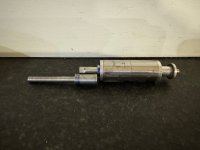
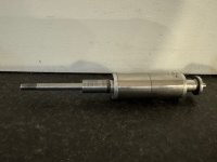
So, here is the rough shaped shaft (steps 1 and 2) from above.

IMG_2879.jpeg
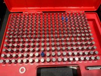
I ended up buying a set of gage pins (another $135 into project) and now I can finally tell what is going on! Wish I had discovered gauge pins earlier in my prototyping journey.
IMG_2880.jpeg
My motor rotor shaft after grinding down is 0.3055 inches in diameter. I bored the hole in my extension shaft so that a 0.305 gauge pin was very tight. It was so easy to tell where I was while boring using the pass fail of gage pins. Then I heated up the extension shaft and slipped it onto the motor rotor.
IMG_2881.jpeg
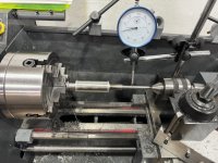
So, all that is leading up to my next step, which is almost like turning the whole assembly between 2 centers.
IMG_2882.jpeg
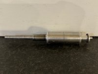
So here is the finished shaft dimensioned for the bearing, compressor and with 1/4” 20 reverse threads.
IMG_2883.jpeg
Now to test it….
———————
I still think there is something wonky. Maybe it is just a bad motor? Maybe the aluminum rotor casting was crooked? Maybe the original shaft is not straight? Maybe something was off when I tried to regrind the shaft. Maybe I could use my shaft bearing as a center rest when forming the shaft.

I may end up spooling it up in the motor and see what happens. If it survives that, I think my next step is WBs idea to try to press the metal center shaft out the aluminum rotor housing that holds the magnets. Then I could make a new one piece shaft between centers that is concentric as possible.
 
Last edited:
I really need a set of gauge pins myself. A one piece shaft is probably the best idea - looking forward to seeing how your turns out.
 
I'm new here and to this process and have found the idea very interesting now that electric motors capable of supporting the idea are available.
Fortunately like many of you I have the equipment to experiment with. I've been looking at a pin gauge set for about a year now and expect to be adding one to my tool collection soon.

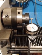
I have a quality four jaw and adjustable 3 jaw chuck and so far managed just under .0005" runout on dial in. But I'm a new hobby machinist and know I can do better after learning how to dial in the 4 jaw after the initial attempt and realizing that the stop I wedged behind the tailstock (still slides after tightening under good pressure) against a casting slat between the bed rails caused a little bit of twist in my 12x28 lathe and a taper at the end of the shaft. I also used a dead center instead of my live center and a follow rest, which is only good for a single pass, after that when the steady tabs go down on the second pass and make contact only near the end of the shaft. it's going to deflect the shaft a bit and affect the depth of cut.

After seeing all of my mistakes I pulled out my adjustable ER40 collet holder and that's when it got real. After dialing it in I conducted a test cut on an 8mm drill rod that I annealed first and got less than .0005" runout on the 5 tenth indicator and confirmed what looked like .0002" range with my 1 tenth indicator although it is the lever type. The finish wasn't all that great so I'm pretty confident the runout I observed in the test area would hold firm at .0002" or less upon polishing out the fine peaks.

Next I'll have to learn how to cut threads to use the left handed die that arrived. I'm planning to use a gear drive arrangement in an effort to minimize friction loss although I have cog wheels and belts for a belt drive. I also have some ceramic bearings coming for the shaft.

I built my first turbo setup over 20 years ago and built several after that so I'm no stranger to turbos and have been sitting on a GTX3584 ball bearing unit for the past 3 yrs slowly making plans for it until now. You all are probably strangers to this, but there's nothing like boost and high compression ratios, my best to date, 11.5:1 in a V6 with water/methanol injection. High compression is the other way of getting rid of turbo lag. Water/meth injection makes a lot possible under boost without breaking the bank. I have a T-76 compressor setup with a 36,000 rpm level to deliver 2+ psi at 40lb/min and 50,000 rpm speed to deliver 7 psi at 40lb/min for the 3.6L at peak power band. I'm going to set a 65,000 rpm limit for the 75,000 rpm max TP motor and then gear it down to 55,000 rpm from the 65k rpm limit. Hopefully it will be powerful enough to get the job done at 5000W continuous which would be mechanically increased with gear reduction.

Now I'm dealing with direct injection (GM 3.6L DOHC) that is a phenomenal game changer. The motor is delivered from the factory with 11.5:1 compression rated for 87 octane fuel, which means I can run even higher compression with water/meth injection and switching to premium fuel. My plans are to build a "Quiet riot" inside a 2010-14 Cadillac CTS Coupe with a base motor that's 305-318 hp and spins to a 7200 rpm redline.

I can really use some help with battery selection. I'm not really interested in, but I'm open to building a battery, but would prefer to buy something already in production delivering close to 100 A/hr in the 50 volt range for the TP4070, 1400Kv 160A motor.

Perhaps two to four of these in parallel, https://www.evwest.com/catalog/product_info.php?products_id=488

Here's an extreme option for long term power delivery between charges for a daily driver.


Shaft test for concnetricity.jpg
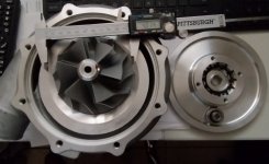
T76 compressor.jpg
 
Are you sure 5kw is enough power to supply the mass flow and pressure of air you require?
No I am not, but it should be sufficient for a significant enough improvement over stock, given that Alex has proved the efficiency level of an electric turbo to be about 40% more efficient in his platform than a traditional turbo, so 2 psi in an electric turbo will be very close to 100 percent of its value vs. 2psi from a traditional turbo minus the energy used to drive it and additional heat.

I have not performed any mathematical proofing yet, but am attributing the ~20% under drive of the motor to multiplication of the 5k watts to 6k watts from a mechanical leverage standpoint and the 9k burst rating to 10.8k watts. Keep in mind 40lb/min is at the high end of the rpm range for the motor.

In this application high rpm is taking the place of huge bottom end torque, which is only as good as the amount you can make stick to the road surface. Second gear is good to 60 mph in the 6 speed tranny in use so that should deliver very good acceleration at low boost let alone at goal. If the motor falls short there are several easy options available to address it.

I could do the TP 5670 at $400 vs. $190 for additional 2000Kw continuous and 10k more rpm at 85k and near 300 A peak capacity, but at this stage I'd rather test the waters keeping the expense to a minimum.
 
With 5kw I think you will produce about 2 to 2.5 lbs of boost at 3000rpm. Proportionally more or less depending on engine speed
 
With 5kw I think you will produce about 2 to 2.5 lbs of boost at 3000rpm. Proportionally more or less depending on engine speed
That's a win because an electric 2 psi is a lot more than a traditional turbo 2psi. I also have a modern engine management system to learn the tuning ropes on. Unlike OBD 1, OBD 2 engine management is torque based and not as straightforward as OBD 1. Torque based systems limit engine power and when the computer detects the motor is making considerably more power than it's programmed for it detunes the motor by closing the throttle down along with other parameters to bring performance back down into spec range. That's the problem many early modifiers of the torque based systems had to overcome in order to successfully boost these operating systems. Drive by wire means you have a computer limitation in that it decides how much of your throttle input it's going to apply.
 
I had a TP4070 in my old set-up and by over-volting the motor I achieved (if I remember) 70k rpm but it was wayyyyyyy over 5kw
Like matnrach said, 2 to 2.5 psi at 5kw is about what I had with my old set up
I have a lot of graph in my thread, you may find something interesting
 
That's a win because an electric 2 psi is a lot more than a traditional turbo 2psi. I also have a modern engine management system to learn the tuning ropes on. Unlike OBD 1, OBD 2 engine management is torque based and not as straightforward as OBD 1. Torque based systems limit engine power and when the computer detects the motor is making considerably more power than it's programmed for it detunes the motor by closing the throttle down along with other parameters to bring performance back down into spec range. That's the problem many early modifiers of the torque based systems had to overcome in order to successfully boost these operating systems. Drive by wire means you have a computer limitation in that it decides how much of your throttle input it's going to apply.
Dont forget that you will need a bypass at high RPM otherwise you will loose power over N/A due to the pressure drop through the compressor at high air mass flowrate
 
Top