You are using an out of date browser. It may not display this or other websites correctly.
You should upgrade or use an alternative browser.
You should upgrade or use an alternative browser.
E-Turbo Controller Code
- Thread starter MkngStffAwesome
- Start date
WB projects
Active member
Can't wait to see an video on how to mess with it because I have apsolutly NOOOO idea how this work  thanks a lot mkgstuff for this share. We are here to help each other and if you need help, let me know I will feel better hahaha
thanks a lot mkgstuff for this share. We are here to help each other and if you need help, let me know I will feel better hahahaMkngStffAwesome
Active member
i need to do a wiring diagram for it all.
dylan.0001@hotm
New member
Hi Michael, Just wanted to say thanks for the R&D that has gone into this. I am running a twincharge setup on a little CA18DET her in AUS. I have recently loaded the sketch onto a little arduino nano but it doesnt seem to fire my ESC. not sure as the code seems different to the one in Alex's youtube vid and the link to the original code in is now broken. I did have to change the name of the code and also adjust the value that Alex had an issue to a lower number than 70000. Any help would be apprecieated.USE AT YOUR OWN RISK
Right i have created a Universal E-turbo controller below is not the complete code but my notes on it so you can see what it does ..
Please provide me with your feed back.
I DON'T like posting code because the internet is full of haters who always think they can do things better, which maybe the case but instead of talking about doing something i actually did it.
The only thing missing from this code is a screen which can be another Project ( that's alot of work TOO ! )
Below are a number of methods of controlling your E-Turbos Max Speed
1 Simple on off switch
2 Adjusting a Potentiometer (POT) AKA a "KNOB"
3 Via the cars Pedal Pressure
4 Via Engine RPM ( This Overrides 2 )
Soft Start to no overload your electrical system.
2-4 and be mix and matched. (The most restrictive one is the actual speed )
SO you can have just a simple Switch "1" OR a switch "1" and engine RPM (4) Or you could have 1,3,4
We then have 4 Out puts which can be used to control various external devices and a saftey feature.
USE AT YOUR OWN RISK
Download Code
USE AT YOUR OWN RISK
I'm out of town at the moment, and if making stuff awesome doesn't get back to you when I get back I can try to help. Though he would be my first choice. Do you happen to have a little oscilloscope of some sort or access to one? That would make troubleshooting a lot easier.Hi Michael, Just wanted to say thanks for the R&D that has gone into this. I am running a twincharge setup on a little CA18DET her in AUS. I have recently loaded the sketch onto a little arduino nano but it doesnt seem to fire my ESC. not sure as the code seems different to the one in Alex's youtube vid and the link to the original code in is now broken. I did have to change the name of the code and also adjust the value that Alex had an issue to a lower number than 70000. Any help would be apprecieated.
dylan.0001@hotm
New member
Hi Alex, Thanks for the reply and for sharing this journey. I dont have an oscilloscope but i may end up buying one as this is the only way I think I can verify that the arduino / sketch is working. I did have it running on the weekend with a servo tester. Moderatly scary without the turbo housing on! Some how i cooked the servo tester (might have doubled the voltage by powering it of the power bank and the ESC) and am waiting on a new one to arrvie. I am also trying to come up with a way to trigger it from my haltech ecu. I have setup it up in the ecu powered by a negative signal. I may need to use a step down voltage converter and use this to power the servo tester. (some pics of my little guy below.) keep in mind this is feeding a much bigger Garrett turbo.I'm out of town at the moment, and if making stuff awesome doesn't get back to you when I get back I can try to help. Though he would be my first choice. Do you happen to have a little oscilloscope of some sort or access to one? That would make troubleshooting a lot easier.
Dylan
Attachments
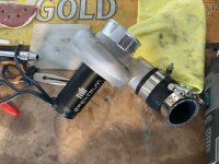
Nice! I used to run a Haltech F9a back in the day. Never gave me a problem. I only removed it because it was programmed through DOS. What is max RPM on that motor and do you have a compressor map for that turbo? Just curious how they match up.Hi Alex, Thanks for the reply and for sharing this journey. I dont have an oscilloscope but i may end up buying one as this is the only way I think I can verify that the arduino / sketch is working. I did have it running on the weekend with a servo tester. Moderatly scary without the turbo housing on! Some how i cooked the servo tester (might have doubled the voltage by powering it of the power bank and the ESC) and am waiting on a new one to arrvie. I am also trying to come up with a way to trigger it from my haltech ecu. I have setup it up in the ecu powered by a negative signal. I may need to use a step down voltage converter and use this to power the servo tester. (some pics of my little guy below.) keep in mind this is feeding a much bigger Garrett turbo.
Dylan
Fwiw, I would use a relay between the Haltech and Arduino. Just good to keep things electrically separated, at least in my mind. It's not necessary but can avoid some issues.
dylan.0001@hotm
New member
Nice! I used to run a Haltech F9a back in the day. Never gave me a problem. I only removed it because it was programmed through DOS. What is max RPM on that motor and do you have a compressor map for that turbo? Just curious how they match up.
Fwiw, I would use a relay between the Haltech and Arduino. Just good to keep things electrically separated, at least in my mind. It's not necessary but can avoid some issues.
dylan.0001@hotm
New member
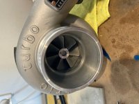
No compressor map as it is a China elec turbo ($400 Aud) with some very sketchy details / graphs that all end with +% power increases that are ambitious.
Max rpm is about 25k and it has loads of talk as it is designed for 1/5 scale RC. I have a purchased this motor as it will probably end up powering a rotrex c15 supercharger that I have ready to go.
Keep in mind I am not trying to boost my car with this turbo. I am trying to eliminate lag on a bigger Garrett that it is feeding up to a certain rpm where it then goes to sleep and valves open to feed air to the Garrett.
Similar to the first little crankcase evac turbo that you put an electric motor on. It was never designed to be the main compressor and hence ran out of puff on my mates motorcycle. This eturbo / supercharger will probably turn off 2k-3k rpm on an engine that revs to 7k-8k
Dylan
Attachments
dylan.0001@hotm
New member
Sorry Siri lol! *loads of torqueNo compressor map as it is a China elec turbo ($400 Aud) with some very sketchy details / graphs that all end with +% power increases that are ambitious.
Max rpm is about 25k and it has loads of talk as it is designed for 1/5 scale RC. I have a purchased this motor as it will probably end up powering a rotrex c15 supercharger that I have ready to go.
Keep in mind I am not trying to boost my car with this turbo. I am trying to eliminate lag on a bigger Garrett that it is feeding up to a certain rpm where it then goes to sleep and valves open to feed air to the Garrett.
Similar to the first little crankcase evac turbo that you put an electric motor on. It was never designed to be the main compressor and hence ran out of puff on my mates motorcycle. This eturbo / supercharger will probably turn off 2k-3k rpm on an engine that revs to 7k-8k
Dylan

Gotcha. I'm back in town. Does the setup still work with the servo tester? I know you said you fried it. You may have damaged the ESC since smaller ESCs tend to have powered BECs. But maybe not. That would be the first thing to look at. MSA's code for the arduino is far better than what I did initially - which was just two servo testers; one set to zero throttle and one set to max throttle. A small, high-speed relay just switched between the two. That does in fact work, and I'd send you my setup if you didn't live on the other side of the planet, but it would probably cost far more to ship than it's worth. The only thing with the arduino setup that I've discovered (and nothing to do with MSA's code), is that you have to be sure to use the correct bootloader for whatever arduino you're using.
So the first thing to do is to check the ESC and make sure that still works. Then get a small, cheap oscilloscope - I use the older version of this one most of the time:
This one looks nice too: https://www.amazon.com/dp/B08L3FRKY...9Y2xpY2tSZWRpcmVjdCZkb05vdExvZ0NsaWNrPXRydWU=
For the money, you can't go wrong with either one. They're good to have for checking sensor outputs, PWM of power supplies, etc. And of course, the output of the arduino. Let us know how you progress and if you have any more questions.
dylan.0001@hotm
New member
Awesome thanks for your help. I have a new servo tester that has arrived and can confirm that the ESC is still healthy and working fine. I may just run with the servo tester at 3/4 speed as I feel the Haltech has got a fair amount of control.Gotcha. I'm back in town. Does the setup still work with the servo tester? I know you said you fried it. You may have damaged the ESC since smaller ESCs tend to have powered BECs. But maybe not. That would be the first thing to look at. MSA's code for the arduino is far better than what I did initially - which was just two servo testers; one set to zero throttle and one set to max throttle. A small, high-speed relay just switched between the two. That does in fact work, and I'd send you my setup if you didn't live on the other side of the planet, but it would probably cost far more to ship than it's worth. The only thing with the arduino setup that I've discovered (and nothing to do with MSA's code), is that you have to be sure to use the correct bootloader for whatever arduino you're using.
So the first thing to do is to check the ESC and make sure that still works. Then get a small, cheap oscilloscope - I use the older version of this one most of the time:
This one looks nice too: https://www.amazon.com/dp/B08L3FRKY...9Y2xpY2tSZWRpcmVjdCZkb05vdExvZ0NsaWNrPXRydWU=
For the money, you can't go wrong with either one. They're good to have for checking sensor outputs, PWM of power supplies, etc. And of course, the output of the arduino. Let us know how you progress and if you have any more questions.
did you end up doing any kind of write-up on how you are charging your battery safely while driving. I have purchased two small charges But when I connect my batteries in series one charger turns off. Might have to look at a charger that is capable of charging 8s or is there something I can do to make them work. I like the small cheap charges that I have because they only connect to the charge leads and charge as soon as they see power. (No pressing buttons and crap)
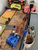
I have a few of those chargers. They're not isolated - meaning the ground goes through from the input to the output. So if you're charging two batteries, you need to isolate them. Another way to do it (and what I initially thought about doing) was to run each one through an inverter, and then a supply and then the chargers. But that's really clunky and inefficient. What I'm using now is a boost converter inside the control box. My battery packs have internal balance boards. So I rely on those to keep the cells balanced, but the boost converter to limit max voltage and current. That way they can't overcharge.
You can look at my control box video for some ideas:
You can look at my control box video for some ideas:
dylan.0001@hotm
New member
Thanks mate i have watched this and it all seems fairly simple but complex at times for my ability. Ok so i may have watched it about 10 times now... Thank god for youtube lol.I have a few of those chargers. They're not isolated - meaning the ground goes through from the input to the output. So if you're charging two batteries, you need to isolate them. Another way to do it (and what I initially thought about doing) was to run each one through an inverter, and then a supply and then the chargers. But that's really clunky and inefficient. What I'm using now is a boost converter inside the control box. My battery packs have internal balance boards. So I rely on those to keep the cells balanced, but the boost converter to limit max voltage and current. That way they can't overcharge.
You can look at my control box video for some ideas:
I am still wondering how i can adapt this to my situation. I am planning on just running 'retail grade' lipos rather than a box of death. I am guessing i will need to work out how i can wire a control / charging box like this to feed to a balance board like the one you have used. Not sure if there is an adapter cable that i can use to convert my 2 x 4s lipo's to the 8s balancing board. I looked at the wiring and i would have 2 - and 8 + wires from the two balance cables coming out of my batteries. Do i need to connect a + to a - so to make the series or do i just connect the two - wires together?
Also are you powering your ESC off the tesla style relay OR are you powering the +- input to the battery box? (Anderson connector in your case)(EC5 connector in my case) Sorry i couldnt work out from the video if the Tesla style relay is to deliver charge power to the battery box or the power to the ESC.
You're on the right track - look at how the balance/charge cables are connected to the cells - you'd just need to make an 8s to two 4s adapter cable. It's a little harder to explain than it is to do - the balance board has 1 ground - that's the cell that the negative-most power cable comes off the batteries. Then it's just a "tap" at every cell until you get to the main positive lead. If you look at it as a stack of 8 cells instead of 2 4s packs, it makes more sense. But please, if you're uncertain, double and triple check that you're not shorting anything out - it could get dangerous. In interest of liability, I'm not telling you how to do it; this is how I would do it. If you do so, you proceed at your own risk (remember: I live in a very litigious country). That said, if you draw it out on paper, it'll make more sense.
Another thing to look at for reference is how the balance boards show they should be connected - like this one: https://www.amazon.com/Equalizer-Ba...f45ce&pd_rd_wg=UAShe&pd_rd_i=B096NNRSMV&psc=1
If that link doesn't work, here's the diagram they give:

FWIW, I use much bigger (more cells, not more current) balance boards that are the exact same construction - I have 24 cells. The only downside is that they either draw power all the time, or you can just have them switch on only when charging (I should actually do that to mine. My boards have pads for an on-off switch - these might too). You wouldn't have low voltage cutoff (neither do I), but you can implement that in the ESC or the arduino code. A true BMS isn't necessary, and in fact puts resistance in the main power path - exactly where you don't want it. In practical use, you never run the turbo long enough to worry about that. At least I don't.
Hope this makes sense.
Another thing to look at for reference is how the balance boards show they should be connected - like this one: https://www.amazon.com/Equalizer-Ba...f45ce&pd_rd_wg=UAShe&pd_rd_i=B096NNRSMV&psc=1
If that link doesn't work, here's the diagram they give:
FWIW, I use much bigger (more cells, not more current) balance boards that are the exact same construction - I have 24 cells. The only downside is that they either draw power all the time, or you can just have them switch on only when charging (I should actually do that to mine. My boards have pads for an on-off switch - these might too). You wouldn't have low voltage cutoff (neither do I), but you can implement that in the ESC or the arduino code. A true BMS isn't necessary, and in fact puts resistance in the main power path - exactly where you don't want it. In practical use, you never run the turbo long enough to worry about that. At least I don't.
Hope this makes sense.
dylan.0001@hotm
New member
Thanks again. It does make sense and I did find some info on wiring the balance cable. It is very important to do one wire at a time and test or kaboom! Thanks for the advice and diagram. Also found this one that explains exactly what you have explained.You're on the right track - look at how the balance/charge cables are connected to the cells - you'd just need to make an 8s to two 4s adapter cable. It's a little harder to explain than it is to do - the balance board has 1 ground - that's the cell that the negative-most power cable comes off the batteries. Then it's just a "tap" at every cell until you get to the main positive lead. If you look at it as a stack of 8 cells instead of 2 4s packs, it makes more sense. But please, if you're uncertain, double and triple check that you're not shorting anything out - it could get dangerous. In interest of liability, I'm not telling you how to do it; this is how I would do it. If you do so, you proceed at your own risk (remember: I live in a very litigious country). That said, if you draw it out on paper, it'll make more sense.
Another thing to look at for reference is how the balance boards show they should be connected - like this one: https://www.amazon.com/Equalizer-Ba...f45ce&pd_rd_wg=UAShe&pd_rd_i=B096NNRSMV&psc=1
If that link doesn't work, here's the diagram they give:
View attachment 385
FWIW, I use much bigger (more cells, not more current) balance boards that are the exact same construction - I have 24 cells. The only downside is that they either draw power all the time, or you can just have them switch on only when charging (I should actually do that to mine. My boards have pads for an on-off switch - these might too). You wouldn't have low voltage cutoff (neither do I), but you can implement that in the ESC or the arduino code. A true BMS isn't necessary, and in fact puts resistance in the main power path - exactly where you don't want it. In practical use, you never run the turbo long enough to worry about that. At least I don't.
Hope this makes sense.

dylan.0001@hotm
New member
Will do mate. I have purchased a heap of stuff (including an oscilloscope) on eBay/Amazon to make your version 2 charging / control box. I will update you when I have some progress. I might try and do a post in the projects section once I get it working. It’s a cool little Datsun 510 that it is going in.
dylan.0001@hotm
New member
Hi alex i think I might be doing something wrong here as I seem to be getting a reading on the oscilloscope but it’s not driving my esc. Was going to reference the reading from the servo tester but I have cooked it too. Seems the don’t like the power being disconnected and reconnected quickly. (Was testing a way to trigger from Haltech if Arduino doesn’t end up working). Should I buy another Arduino and start again? I’m at a loss…


