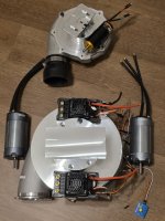
I purchased the VESC version 2, 200A model last year because it was priced well for current level it could support and I wanted to keep the initial build low budget until I could produce results to justify using the "Money Hammer" on higher performing equipment. The motor is a TP 4070, 1400Kv, 75k rpm unit driven by 16s voltage with an ~1.8:1 belt drive.
Months passed before I finally decided to try setting everything up using the VESC, given how intimidating it appeared to be with all of the app functions and the poor detail provided on screen regarding what they do. Surprisingly it was easy to setup as far as demonstrating basic connectivity and signs of operation.
Performance is where the challenge came in. It was apparent to me that the compressor was not spinning up near max speed unloaded, ~ 40k rpm anticipated and instead was faulting out at 25k rpm after voltage, current and ERPM limits were corrected to get past the 20k rpm limit first encountered. There was also the matter of disabling braking as that could potentially result in loosening of the retaining nut and compressor wheel given the diameter relative to the shaft to wheel contact surface.
It's amazing how unhelpful most of the info I encountered was regarding how to disable braking. It's a straight forward question, but it yielded not one straightforward answer and I finally settled on setting motor current max brake, battery current max regen, and max ERPM reverse to nearly 0.
After giving it a lot of thought and noting that the same fault was repeatedly being set but varying depending no the rate of throttle input, I considered all things associated with current and noted that my experimental power supplying wires were probably only suitable for about 20 amps and a quick grab immediately following a motor cutout revealed both wires were hot to the touch through the insulation so I'll be switching them out for 8 awg.
I'm not sure how the VESC app calculates current but I put an ammeter in line and only measured about 60 amps at cutout. With what I was able to accomplish with the changes made in programming the blower sounds like it is performing as intended until it faults out.
I also discovered that I'll need to upgrade from the .5" belt to a 1" belt system. If the power wire upgrade does not eliminate the fault incidents I'll plan to retire the VESC and get a traditional non-complicated/over engineered ESC. Initially when I started working with it I noted that the motor was heating up seemingly quickly over brief runs that I did not observe with a small 80amp ESC in use. It appeared to work itself out as I adjusted parameters in the VESC app. I may dump it regardless because it is overly complicated for the job it is intended to do here.


