Shmedium size positive displacement blower span by a Castle 2535? I know, I know…

StavTech

New member
Hi. While the Castle motors seem to be great at spinning up a speedmaster centri, could they manage to do a small/medium size positive displacement blower like a M62/M90 to 15-18000rpm?

Reason being, I don't want to use it for top end or even constant power, i want it to replace my 75-100 shot of nitrous as torquefill/antilag for about 500-1000rpm in the midrange to get my turbo on song for certain circumstances (straight line stuff).
Nitrous is a massively inconsistent pain in the ass so so I’ve had enough of it.

Because of the very short amount of time it will be used, a second or so at a time, the fact they’re not efficient etc is not an issue.

Reason I’d prefer one over a centri is partly cost and availability where I am, but also zero issues with it being in the usable part of the compressor map- If it spins, it flows the air, end of.

But is it viable, or no? I know they take more to spin them than a positive, but they also spin much slower.
But I also don’t know enough about electric motors to know if they work well enough at that rpm vs how they’re normally span on a Speedmaster P2 setup.

Thanks
 
Last edited:
wouldn't they be very restrictive when not spinning?

The other thing that comes to my mind is inertia, how much weight is in the rollers that the motor needs to get moving from 0 rpm to 15k in a short span of time as compared to a centrifugal compressor?
 
wouldn't they be very restrictive when not spinning?

The other thing that comes to my mind is inertia, how much weight is in the rollers that the motor needs to get moving from 0 rpm to 15k in a short span of time as compared to a centrifugal compressor?
It would be massively restrictive not spinning, but so would a centrifugal, just not as much.
Either way, no issue as it will would be totally bypassed.

Ref weight/inertia, no idea, that’s why I posted to see if someone had any decent factual info.

If it’s just a ‘not sure, might work’ from the people with experience on here, I’ll just have to try it.
I'll have to disagree with the presumption that the centrifugal will be significantly restrictive for two reasons, first the area of airflow needs to be considered, given the apparent size of the P2 compressor housing, chances are pretty good that appreciable restriction to airflow when the compressor is not in operation would be at an engine rpm level that is not likely to have the compressor sitting idle (performance range). Second, Alex made a video on this very topic and from what I recall it is for the most part a non issue. It also depends on engine size relative to the P2, using his engine displacement and performance level as a reference point. If your motor doesn't move the cfm his motor needs naturally aspirated, any effect will be even less for your motor.

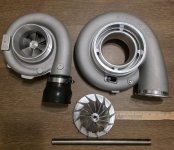
I just received my new compressor housing and wheel to make the system I want to run which is based on a GTX5533 turbo. The prototype I built seen next to it is a T-76 turbo. The GTX wheel is 5.25" in max diameter, the compressor outlet is just shy of 3" in internal diameter, which is about the size of my MAF sensor internal diameter and the overall area of the air passages into and out of the compressor are considerable enough in size to suggest that there would be little to no appreciable restriction to flow when not in use except at likely very high airflow demand where it would likely be running.

In my experience since you already have a turbo in place, I'd build the motor with a higher compression ratio, make sure I have the most efficient and responsive turbo on it and call it a day. There are too many additional friction points in addition to rotational mass increase/drag, the P2 has 3 bearings and one impeller vs at least 4 bearings, two rotors and gears for the blower. High compression and boost changed my whole outlook with turbocharging, there was no lag, just manual transmission crushing torque. I refuse to build a turbo motor with less than 11:1 compression and plan to build one with 13:1 compression now that we have direct injection onboard.
 

Attachments

  • New compressor.jpg
    New compressor.jpg
    295.9 KB · Views: 7
Last edited:
I'll have to disagree with the presumption that the centrifugal will be significantly restrictive for two reasons, first the area of airflow needs to be considered, given the apparent size of the P2 compressor housing, chances are pretty good that appreciable restriction to airflow when the compressor is not in operation would be at an engine rpm level that is not likely to have the compressor sitting idle (performance range). Second, Alex made a video on this very topic and from what I recall it is for the most part a non issue. It also depends on engine size relative to the P2, using his engine displacement and performance level as a reference point. If your motor doesn't move the cfm his motor needs naturally aspirated, any effect will be even less for your motor.

I just received my new compressor housing and wheel to make the system I want to run which is based on a GTX5533 turbo. The prototype I built seen next to it is a T-76 turbo. The GTX wheel is 5.25" in max diameter, the compressor outlet is just shy of 3" in internal diameter, which is about the size of my MAF sensor internal diameter and the overall area of the air passages into and out of the compressor are considerable enough in size to suggest that there would be little to no appreciable restriction to flow when not in use except at likely very high airflow demand where it would likely be running.

In my experience since you already have a turbo in place, I'd build the motor with a higher compression ratio, make sure I have the most efficient and responsive turbo on it and call it a day. There are too many additional friction points in addition to rotational mass increase/drag, the P2 has 3 bearings and one impeller vs at least 4 bearings, two rotors and gears for the blower. High compression and boost changed my whole outlook with turbocharging, there was no lag, just manual transmission crushing torque. I refuse to build a turbo motor with less than 11:1 compression and plan to build one with 13:1 compression now that we have direct injection onboard.
Ok, a few points here.

Centrifugals.
1- I know they are restrictive. Ive tested it. Im presuming zero. Not wildly, but way way too much.
2- it’s irrelevant anyhow as even if I was using a centrifugal, and Im not, it would be fully bypassed regardless.

The engine.
Making it high comp in some aim to get spool is pointless. Again, from experience.
And why make myself det limited by doing that to gain, basically nothing. Certainly not what I want to achieve anyhow.
Unless you magically think I can still run 35psi on pump gas at 11:1 somehow.
And turbo setup wise, very little to zero to be improved.

The next bit about friction and stuff ive zero idea what relevance that is to anything Im talking about.

And none of it answers anything i was asking unfortunately.
Understand that you posted no specifics whatsoever about your setup, not a single one to justify the attitude you seem to have regarding my input. If anything my mistake was not pointing that out first.

Your comment in red text above begs the question of how much do you understand about any of what you are asking if you can not see the connection between "...friction and stuff" along with inertia which another member has pointed out in regards to any brushless motor's ability to spin a given power adder fast enough to achieve and sustain the intended boost level as long as needed and at what expense of battery power.

Just think about the ease of spinning a single compressor wheel with 2 ceramic bearings which turned by hand will spin freely for a few seconds vs. all of the components involved in the rotating assembly of the M62/90 and how attempting to free-wheel it in the same manner will work out.
I didn’t post specifics on my engine as it is 101% irrelevant to what I’m asking about.

I’m asking purely about one thing. And was hoping for answers from experience of what I’m asking regarding motor power etc. And have had zero so far.

And the irrelevance is because…

“All of the components”- There are two separate rotating parts, and 4 roller bearings. Not a lot.
They don’t take a lot to turn by hand, and need to go to about 1/3-1/4 what the P2 is, so it seemed viable enough to consider it.

I know it won’t be “as” easy, if I thought it was I wouldn’t be asking hoping for experienced advice. I’ve never messed with these electric motors and most people’s theories are nothing like experienced reality.
You are incorrect although confident. At a minimum the desired airflow at your secret goal is important to know and that depends on the motor, as many of those planning and building on this forum use math and a good bit of it to make decisions on what to buy, how to build it and whether or not they should.

My best guess is that you're not getting much in the area of info because most here if not all have already concluded that electrically driving a traditional supercharger is highly inefficient compared to the tested standard (P-2) here and have spent no time investigating it.

There are four roller bearings, two rotors and also a shaft which has some type of bearing(s) plus gearing to link it to the rotors. You have no reference point regarding how much horsepower/Kw power is needed to rotate that blower at the desired CFM. On the other hand, those here making plans with the P-2 do have that information and can use it to calculate the requirements and limits of their design.

Theory is a very good place to start, especially when the scientific method is highly involved in the process. It is more reasonable and practical based on what has been tried here, than your assumption without any experience that the sum of all those extra components/parts in the M series blowers do not constitute the need for much more energy input than the simplicity of a single compressor wheel, a short shaft and two or three bearings.

You need to find a site that can give you the driven power demands of those blowers, and a compressor map and do the math yourself.
 
FWIW
Alex has tested his v8 to measure loss in performance with the P2 not running, and found it's significant. I've done similar tests on a smaller engine (13b rotary) and found the losses below 7000 rpm were inconsequential and only became an issue above that, somewhere around 25lbs/min of flow seems to be where it crosses over.
Also: as mentioned, no-one on here has tried what you are suggesting but yeah, much more power to accelerate and drive a blower is going to make it way more difficult to get good results than if you chose a centrifugal - imo.
 
Last edited:
FWIW
Alex has tested his v8 to measure loss in performance with the P2 not running, and found it's significant. I've done similar tests on a smaller engine (13b rotary) and found the losses below 7000 rpm were inconsequential and only became an issue above that, somewhere around 25lbs/min of flow seems to be where it crosses over.
Also: as mentioned, no-one on here has tried what you are suggesting but yeah, much more power to accelerate and drive a blower is going to make it way more difficult to get good results than if you chose a centrifugal - imo.
Yes he did, but it was around 4000 rpm and up which is not a frequent rpm to hit for normal driving off boost. Again it depends on the engine displacement as you demonstrated above, however a bypass is important for all range performance, or variable charger operation to offset the obstruction..

I don't believe I'll need one because my compressor wheel inlet is nearly an inch greater in diameter than the P2 at 91mm and the compressor housing area appears greater in size as well. There are so many factors to consider when assessing this theoretically, like for instance his motor being built to some degree and already having a higher flow demand than the same motor in stock trim.
 
FWIW
Alex has tested his v8 to measure loss in performance with the P2 not running, and found it's significant. I've done similar tests on a smaller engine (13b rotary) and found the losses below 7000 rpm were inconsequential and only became an issue above that, somewhere around 25lbs/min of flow seems to be where it crosses over.
Also: as mentioned, no-one on here has tried what you are suggesting but yeah, much more power to accelerate and drive a blower is going to make it way more difficult to get good results than if you chose a centrifugal - imo.

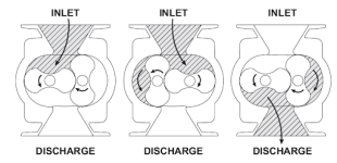
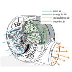
Its obvious when you look at a positive displacement setup, big long heavy rotating hunks of metal that are designed to stop air flowing through them, vs a centrifugal that allows air to flow past the compressor when it isn't spinning. The compressor wheel is obviously lighter, easier to get moving and accelerate up to speed. Sure the centrifugal will be more of an obstruction to flow than just a pipe, but the positive displacement blowers are designed to not let air past the rotors so that the air doesn't escape back out past them.

1759197213960.png1759197336096.png
 
however a bypass is important for all range performance, or variable charger operation to offset the obstruction..
It actually isn't important at all on my particular setup (13B rotary with P2). Below 7000rpms and full throttle there isn't enough restriction to make any difference in power. If you think about the system as a whole, the only restriction that makes a difference right up to that 7000rpm wide open point, is the THROTTLE! And the throttle is under the control of my right foot. Given that, at any point over 7000rpm (other than decel.) I'm going to have my foot hard down anyway and eSC will be activated, there is no need for a bypass.
 
Last edited:
It actually isn't important at all on my particular setup (13B rotary with P2). Below 7000rpms and full throttle there isn't enough restriction to make any difference in power. If you think about the system as a whole, the only restriction that makes a difference right up to that 7000rpm wide open point, is the THROTTLE! And the throttle is under the control of my right foot. Given that, at any point over 7000rpm (other than decel.) I'm going to have my foot hard down anyway and eSC will be activated, there is no need for a bypass.
The assumed qualifier to mean at any range of operation in the absence of supercharger use the motor might find itself that creates an obstruction goes without saying. No obstruction, no need, but the OP has not shared whether he/she is boosting a big block or a lawn mower engine so in the absence of that knowledge it is important to know and the data you've included is good in that it helps establish a baseline limit that can be determined by an identified flow point to expect an obstruction, as well as what Alex's graphs indicate.
 
Top