You are using an out of date browser. It may not display this or other websites correctly.
You should upgrade or use an alternative browser.
You should upgrade or use an alternative browser.
S2000 Rotrex + Electric Motor
- Thread starter SteveB
- Start date
Do you think a single injector will provide good cylinder to cylinder fuel matching? I've been thinking an FMU may be better at this, as it hits all 4 injectors the same. I asked ChapGPT and she(?) says the single injector will be fine. I'll probably start with the combination and then consider getting rid of the FMU.
You're not running high boost so it should work fine however you could also check to see if there is a fuel injector replacement that flows a little bit more fuel than your current stock injectors and swap them in. The stock computer can adjust fuel within a certain range ~10% to counter the extra fuel, or if you can use one of the adjustable fuel pressure regulators I've seen available for the S2000 you can adjust the pressure downward a little to achieve the equivalent flow to the stock injectors and still maintain the increased flow potential higher up.Do you think a single injector will provide good cylinder to cylinder fuel matching? I've been thinking an FMU may be better at this, as it hits all 4 injectors the same. I asked ChapGPT and she(?) says the single injector will be fine. I'll probably start with the combination and then consider getting rid of the FMU.
I started with this stuff some years before direct injection and had lots of injector flow specs where many injectors were interchangeable with little to no mechanical mods necessary to fit them on domestic vehicles, Honda may be very different.
I think I finally got the VESC reliable. It took a lot of trial and error and fooling around, but in the end, I believe my setup is ending up better because of the VESC. I wanted something that I could just get in the car and drive, and not worry about the supercharger or battery (or fluid levels, etc). It would have been more difficult getting a flat boost control, controlling the battery, cooling, etc, without it, but it has been a lot of work. If anyone wants to use a VESC, I can help, but be prepared to struggle some for a while.
It has a wonky On and Off input that took me 4 different circuits before I got it to shut down reliably, but I finally got there. I'm a retired analog circuit designer, so I tried my best to use a transistor, but had to give in and use a micro relay. I don't have a separate switch between the battery and ESC, so I rely on the ESC shutting down when the engine stops, to not drain the battery. You can't simply switch off 12V. I switched over to the micro relay when I realized that if the 12V battery ran down, the VESC would wake up and eventually drain the blower battery. I have a design and the parts to build a solid state power switch for the battery, but as Elon says "No part is the best part". So far I don't need it.
Then there is FOC motor control, which is very sensitive to some motors (like mine) and took days of trial and error before it worked well with my motor. Now that I know how it works, I could get a motor optimized in a hour or so. A basic BLDC controller just works straight out of the box (or so I'm told).
It took me a while before I realized there is a setting that gradually limits motor current at high eRPM. The default was something like 80k eRPM, which I didn't worry about until I realized that is only 5.7k rotor rpm for a 14 pole motor. The motor really woke up when I changed that to 120k.
It had settings that should have allowed it shut down gently with a low cell voltage in the battery, but after fooling around for a few days, I realized those settings didn't do anything. Apparently, it is hard coded for LiPo, and ignores the settings I put in for LTO. I was able to find a work-around, by moving the battery management to the Arduino, but there goes another week of learning about how to move data across CAN. I'm a hacker, not a programmer, so it takes me a while.
These are just some examples of my VESC trials. There are others..
But there is a lot of good as well. Changing motor control over to a CAN bus interface was painful, but it allows me to command motor duty cycle when under boost, and command motor current when shutting it down. DC spools the motor up at max motor current, then the current drops back when the motor rpm gets to where it should be. That gives fastest spool up. A Motor Current command of 0 amps allows it to coast down gently and stay spooled up between shifts. This worked great on the bench, but I haven't tested it much on the car. I have a table in the Arduino of DC vs RPM that it uses to keep the boost constant. I can shape the boost curve anyway I'd like, or have multiple boost curves that I can set from the driver's seat. (for now, I have the Cruise Control switch sent to the Arduino). The CAN bus also gives good noise immunity, which fixed some of the problems I had during bench testing.
The VESC sends back motor temperature acoss CAN which I use to control the fans, and also to slowly shut down the motor if it gets too hot. Battery status is on the CAN bus, so the Arduino gradually reduces power when the cell with the lowest voltage in the pack gets low. I used a VESC compatible BMS that talks over CAN. But it only charges the battery and won't maintain the battery (as I found out late in the design) ie it shuts the charger down after the battery is charged. So I used the Arduino over the CAN bus to control the battery charger, so now I can do whatever I want with it. I have a dumb $30 dc upconverter for the charger, but I can get away with that because the Arduino is in control of it.
I have to admit, my setup is more complicated than most people like, but I have enjoyed this so far, and hopefully it will end up working seemlessly and hands-off in the car. I spent a lot of time testing everything in my spare bedroom (with ear protection and a very understanding wife) and I think that paid off. Everything seems to be working well after 3 or 4 test drives. The main problem is getting the fueling and tune right.
If anyone is interested, I have a complete set of schematics and documentation, which is probably about 95% finalized. The main thing that is changing is control of the engine tuning, which will mostly be done by the Arduino plus some hardware that is still tbd.
Below is a link to the schematics and Arduino code.
 drive.google.com
It has a wonky On and Off input that took me 4 different circuits before I got it to shut down reliably, but I finally got there. I'm a retired analog circuit designer, so I tried my best to use a transistor, but had to give in and use a micro relay. I don't have a separate switch between the battery and ESC, so I rely on the ESC shutting down when the engine stops, to not drain the battery. You can't simply switch off 12V. I switched over to the micro relay when I realized that if the 12V battery ran down, the VESC would wake up and eventually drain the blower battery. I have a design and the parts to build a solid state power switch for the battery, but as Elon says "No part is the best part". So far I don't need it.
Then there is FOC motor control, which is very sensitive to some motors (like mine) and took days of trial and error before it worked well with my motor. Now that I know how it works, I could get a motor optimized in a hour or so. A basic BLDC controller just works straight out of the box (or so I'm told).
It took me a while before I realized there is a setting that gradually limits motor current at high eRPM. The default was something like 80k eRPM, which I didn't worry about until I realized that is only 5.7k rotor rpm for a 14 pole motor. The motor really woke up when I changed that to 120k.
It had settings that should have allowed it shut down gently with a low cell voltage in the battery, but after fooling around for a few days, I realized those settings didn't do anything. Apparently, it is hard coded for LiPo, and ignores the settings I put in for LTO. I was able to find a work-around, by moving the battery management to the Arduino, but there goes another week of learning about how to move data across CAN. I'm a hacker, not a programmer, so it takes me a while.
These are just some examples of my VESC trials. There are others..
But there is a lot of good as well. Changing motor control over to a CAN bus interface was painful, but it allows me to command motor duty cycle when under boost, and command motor current when shutting it down. DC spools the motor up at max motor current, then the current drops back when the motor rpm gets to where it should be. That gives fastest spool up. A Motor Current command of 0 amps allows it to coast down gently and stay spooled up between shifts. This worked great on the bench, but I haven't tested it much on the car. I have a table in the Arduino of DC vs RPM that it uses to keep the boost constant. I can shape the boost curve anyway I'd like, or have multiple boost curves that I can set from the driver's seat. (for now, I have the Cruise Control switch sent to the Arduino). The CAN bus also gives good noise immunity, which fixed some of the problems I had during bench testing.
The VESC sends back motor temperature acoss CAN which I use to control the fans, and also to slowly shut down the motor if it gets too hot. Battery status is on the CAN bus, so the Arduino gradually reduces power when the cell with the lowest voltage in the pack gets low. I used a VESC compatible BMS that talks over CAN. But it only charges the battery and won't maintain the battery (as I found out late in the design) ie it shuts the charger down after the battery is charged. So I used the Arduino over the CAN bus to control the battery charger, so now I can do whatever I want with it. I have a dumb $30 dc upconverter for the charger, but I can get away with that because the Arduino is in control of it.
I have to admit, my setup is more complicated than most people like, but I have enjoyed this so far, and hopefully it will end up working seemlessly and hands-off in the car. I spent a lot of time testing everything in my spare bedroom (with ear protection and a very understanding wife) and I think that paid off. Everything seems to be working well after 3 or 4 test drives. The main problem is getting the fueling and tune right.
If anyone is interested, I have a complete set of schematics and documentation, which is probably about 95% finalized. The main thing that is changing is control of the engine tuning, which will mostly be done by the Arduino plus some hardware that is still tbd.
Below is a link to the schematics and Arduino code.
Electric Supercharger - Google Drive
drive.google.com
i read about your fueling challenge and maybe this could be an option: For a similar purpose, many direct injectors setup cannot be upgraded to add fuel over the factory limits. Peoples add 1-2 PI injectors before throttle body (or 4 smalls with an extra intake adapter) and use the Splitsecond AIC1 controller that read RPM and pressure to map the injector duty cycle thru a basic software. It isn't perfect like explained by others but it remain safer than a plastic methanol system and could use the same fuel. A quick google search for ''Secondary injection fuel kit'' would get you a bunch of options including injectors adapter to silicone hose or else....You can program the controller to only trigger the extra injector at some boost or rpm and if you read boost after the throttle,(intake plenum) you can avoid spraying against a closed throttle.
i'm also curious to know if the Rotrex oil pump needs significant extra power compared to other dry setup to run ?
i'm also curious to know if the Rotrex oil pump needs significant extra power compared to other dry setup to run ?
Thanks for the suggestions. If I go with an aux injector, I don't plan to use an off the shelf controller, but instead do my own control with the existing Arduino. The coding will be pretty simple. I'll probably have a fuel table for the one injector, based on rpm and boost. Look up injector duty cycle from the table, add in some injector dead time, and fire the injector through a FET at a frequency of around 200 Hz. I'll have to include throttle position somehow. The blower is only powered when the throttle is close to wide open. This sensor data is already in the existing code which controls the supercharger, so the only additional wiring needed is to hook up the injector. Total cost should be less than $250 - an injector plus some fittings and a bung welded to the charge pipe. I briefly saw something about injector adapters, I'll definitely check out the references you show. Can you tell me more about how/why they use multiple injectors before the throttle plate?i read about your fueling challenge and maybe this could be an option: For a similar purpose, many direct injectors setup cannot be upgraded to add fuel over the factory limits. Peoples add 1-2 PI injectors before throttle body (or 4 smalls with an extra intake adapter) and use the Splitsecond AIC1 controller that read RPM and pressure to map the injector duty cycle thru a basic software. It isn't perfect like explained by others but it remain safer than a plastic methanol system and could use the same fuel. A quick google search for ''Secondary injection fuel kit'' would get you a bunch of options including injectors adapter to silicone hose or else....You can program the controller to only trigger the extra injector at some boost or rpm and if you read boost after the throttle,(intake plenum) you can avoid spraying against a closed throttle.
i'm also curious to know if the Rotrex oil pump needs significant extra power compared to other dry setup to run ?
Good question about the oil pump. Rotrex, likes most blower companies, show adiabatic efficiency on their blower maps, which normally only includes losses which results in heat going into the compressed air. It does not include losses which heat the oil up, or heat the compressor housing up, etc. You can accurately calculate output air temp, but you cannot accurately calculate supercharger shaft input power. Rotrex claims their traction drive is "up to 97% efficient". That is about all I have found. I am not using an oil cooler like they recommend, as my blower does not run all the time. If the oil pump was consuming a lot of power, it would heat the oil up. The oil does get warm, but not hot enough in a couple of minutes of operation to get too concerned with. Also, I can kindoff estimate the power the electric motor is putting out, and it is in the ball park of assuming relatively low mechanical loss. I'm directly driving the blower, so I have no belt loss.
Port Injector?What is a "PI injector"
I put together a charge pipe injector test case using a Bosch EV14 compact injector. I didn't use the Deka recommended above only because I found a perfect holder for the EV14. I used a 360cc injector with a cone spray, driving it with an Arduino + MOSFET that pulse width modulated the injector. I injected gasoline at 50psi into the air stream of a leaf blower. The picture shows the result. The spray pattern is much more tightly focused than I anticipated. It will shoot 10 feet through the air if I point it into free air. (I did this outside in the wide open, with a fire extiguisher near!) I also tried holding the charge pipe so the leaf blower blew the gas into my charge pipe. It pretty much blasts right across the charge pipe, hits the other side, and splashes liquid gas everywhere. When it hits the charge pipe, a lot of the mist turns into large drops of gasoline so that liquid gas runs out of the end of the charge pipe. I tried all angles between perpindicular to the flow, to shooting it almost straight down the pipe. When it shoots straight down the pipe, it remains a tight stream, until it hits the 90deg elbow, turns and then splashes out toward the throttle body. When it turned the corner of the 90, it hugged the outside and entered the TB as a narrow stream of spray + liquid. I tried spraying into the flow as well. The flow seemed to disrupt the spray, so when it came back the other way, the drops were larger. Perpindicular looked to be the best, as the shear from the air flow helped disperse the spray, But any way I tried it, quite a bit of the gas ends up liquid coming out of the 90deg bend to the throttle body. I never did get a mist that came anywhere near filling the charge pipe. Bosch makes EV14's with wider spray patterns, but I couldn't find any that were much wider. My conclusion is the EV14 will not work well enough.
I'll take a look at the Deka to see if the spray pattern is better, if I can find the data on it. I also read that the tight spray pattern of the EV14 is typical of modern injectors - they aim directly at the intake valve and let the hot valve do the atomization. Older, pintle style injectors apparently generate a finer mist. I may try one. The problem is they are a lot larger than the EV14, and my space is limited. I read that old throttle body injectors may also be better.
I also am interested in trying something called a "Fuel-It" charge pipe injector. I contacted them for more data.
Any suggestions?
Attachments
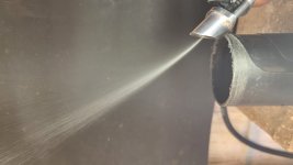
I worked with injectors using lbs/hr units, if your 360 cc equates to ~34 lbs/hr at 50 psi you need to go to a smaller flow injector and a higher fuel pressure. 50 psi is low average for port injectors. For better misting the trend is always high pressure no matter what the flow rate. When I looked at your picture I immediately concluded that's not what you want, that looks more like a jet stream than a spray mist and you may even need to resort to a stainless steel or brass water/methanol injection nozzle to get what you need using a solenoid for on/off operation.I put together a charge pipe injector test case using a Bosch EV14 compact injector. I didn't use the Deka recommended above only because I found a perfect holder for the EV14. I used a 360cc injector with a cone spray, driving it with an Arduino + MOSFET that pulse width modulated the injector. I injected gasoline at 50psi into the air stream of a leaf blower. The picture shows the result. The spray pattern is much more tightly focused than I anticipated. It will shoot 10 feet through the air if I point it into free air. (I did this outside in the wide open, with a fire extiguisher near!) I also tried holding the charge pipe so the leaf blower blew the gas into my charge pipe. It pretty much blasts right across the charge pipe, hits the other side, and splashes liquid gas everywhere. When it hits the charge pipe, a lot of the mist turns into large drops of gasoline so that liquid gas runs out of the end of the charge pipe. I tried all angles between perpindicular to the flow, to shooting it almost straight down the pipe. When it shoots straight down the pipe, it remains a tight stream, until it hits the 90deg elbow, turns and then splashes out toward the throttle body. When it turned the corner of the 90, it hugged the outside and entered the TB as a narrow stream of spray + liquid. I tried spraying into the flow as well. The flow seemed to disrupt the spray, so when it came back the other way, the drops were larger. Perpindicular looked to be the best, as the shear from the air flow helped disperse the spray, But any way I tried it, quite a bit of the gas ends up liquid coming out of the 90deg bend to the throttle body. I never did get a mist that came anywhere near filling the charge pipe. Bosch makes EV14's with wider spray patterns, but I couldn't find any that were much wider. My conclusion is the EV14 will not work well enough.
I'll take a look at the Deka to see if the spray pattern is better, if I can find the data on it. I also read that the tight spray pattern of the EV14 is typical of modern injectors - they aim directly at the intake valve and let the hot valve do the atomization. Older, pintle style injectors apparently generate a finer mist. I may try one. The problem is they are a lot larger than the EV14, and my space is limited. I read that old throttle body injectors may also be better.
I also am interested in trying something called a "Fuel-It" charge pipe injector. I contacted them for more data.
Any suggestions?
Take a look at this demonstration, I have ordered nozzles from McMaster-Carr for practical prices as a resource. If you're going to spray gasoline I'd keep the nozzle as close to the throttle body as possible and preferably injecting directly into the intake due to its flammability.
You would likely need to add a second fuel pump (high pressure) in series to the injector and an extra pressure regulator in the loop for the add on injector. It can be looped so that the bleed off fuel goes around to the inlet of the secondary pump to avoid dead heading the pump.
Last edited:
Thanks for the suggestions. I'd like to tap off the existing fuel rail, so the pressure is what it is. I emailed the "Fuel-It" people and they claim their injector will work, so I'll give it a try and show the results here. Can I pulse width modulate a solenoid fast enough to control a water/methanol nozzle? I think I need about a 3 to 1 range in fuel flow from the aux nozzle to cover the RPM and boost range I'm expecting. I could also use 2 nozzles and 2 solenoids to get the needed range. Can I run a water/meth nozzle from my fuel rail, or does it require its own pump?
Oh - just saw your video...
Oh - just saw your video...
There are many different types of performance fuel pump options in this case external that have various fittings that would allow you to feed it directly from your existing fuel rail. Walbro fuel pumps is one option although I would never again use one of their in tank performance pumps. The external pump would be a simple circuit with a "T" fitting at the inlet and a "T" fitting at the outlet which feeds a second adjustable fuel pressure regulator and whose outlet would loop back to the inlet "T" fitting so once the desired pressure is reached the excess fuel goes into a loop pattern circling back to the inlet end and back through the pump repeatedly.Thanks for the suggestions. I'd like to tap off the existing fuel rail, so the pressure is what it is. I emailed the "Fuel-It" people and they claim their injector will work, so I'll give it a try and show the results here. Can I pulse width modulate a solenoid fast enough to control a water/methanol nozzle? I think I need about a 3 to 1 range in fuel flow from the aux nozzle to cover the RPM and boost range I'm expecting. I could also use 2 nozzles and 2 solenoids to get the needed range. Can I run a water/meth nozzle from my fuel rail, or does it require its own pump?
Oh - just saw your video...
I don't believe a water/meth solenoid would need to be pulsed in the manner that a fuel injector would, for one its duty cycle is far less in that it would only be activated during boost where fuel injectors are run continuously with the motor and need to have heat management. Water/meth nozzles will require the addition of the inline pump in order to achieve the kind of pressures they need to generate a fine mist. A fuel pump capable of over 100 psi of pressure should work fine. It's been a while since I've worked with them so I'm not sure how much above 100 psi they reach now.
Yes PI=Port injector (low pressure)Port Injector?
The reason why they put more than one is just for more flow.
And yes the atomisation won't be ideal but it is not much different from old carburetor engines where the spray is not that close to intake valves and hit a couples walls and curves before reaching the combustion chamber. (I dont talk about tunel ram V8 but multi-tubes intakes from old shcool engines...)
You already have optimised atomisation from factory injectors. this is just extra fuel under boost....you may waste some but if you really need the best you would have to drill the intake or add a sandwhich plate between intake and head for extra nozzles if you have the place...
For injectors, an economy option is to look at factory 4cyl cars with good power figured (turbo with 4 factory PI injectors is a good choice) and you can get connectors and stuff around to build your kit for little money.
As stated above, your spray patern is kind of special, if you look at some video for injector cleaning, it is a lot more V shaped than yours....
And methanol nozzle won't work at low pressure, i run mine above 200psi and at low pressure it is looking more like a garden hose spray... . I would stick to fuel injectors designed for that purpose, they have the valve and the nozzle in a single unit.
If you T on your factory line with an extra pump, be careful to avoid overloading the return line or droping the factory fuel rail pressure by sucking too much.... you may try it first on the factory pump without extra return and check for fuel pressure drops under max load....You would see if an extra pump is needed because it drops or not but you would need a cabin gage to look att it....
You may even use a voltage converter on factory pump to boost it a bit by rising the voltage to 15-16v triggered by maybe the turbo ...
Last edited:
This is a copy of a post I did on another forum:
Here is an update on my fuel system. I have given up on an auxilary injector. I tried 2 different approaches, including the Fuel-It charge pipe injector. My tests with a clear plastic pipe and a leaf blower show almost no vaporization, just a bunch of spray that ends up as liquid everywhere. I measure the leaf blower with a MAF meter, and it is putting out good air flow. I have tried 2 FMU's, and the folks that say they don't work great are pretty much correct. So on to version 3. My motivation is to keep the stock ECU, as I have discussed before. The electric supercharger is completely off except at full throttle, so the stock ECU works perfect off boost. I hate to give that up. I have looked at piggy back ECU's, but the one's I have seen all involve a lot of wiring. There used to be a plug and play Haltech for the AP1, but its not available anymore. But even that is more wiring than I want. It goes between the ECU and the Injectors. I think I have a better solution that is in the works. I have tested an approach that does not go between the stock ECU and injectors, but is in parallel with it. The idea is to add to the existing pulse to the injector, not replace the stock pulse. The ECU injector driver is a MOSFET that acts as a switch to ground. I am adding another MOSFET switch to ground that I turn on at the end of the existing pulse to extend it. The only wiring is to tap into the stock injector wires (no cutting). My test show the new switch turns on within 20 microseconds of the stock pulse turning off. Since it takes over 100us for the injector to turn off, there is no gap between the pulses. It acts as a single pulse to the injector. The stock injectors have quite a bit of extra capacity, so they should be able to handle close to 6psi of boost up to about 8k rpm - I may have to reduce the boost above that. Im a retired electrical engineer, so the circuit design is something I can do. So the whole thing is an Arduino with 4 MOSFETs and some misc stuff. The Arduino will have a fuel map based on Boost and RPM. The fuel map will actually be a map of added pulse width vs RPM and Boost. I tested the circuit on one cylinder in the garage (revving the engine up in neutral.) The pulse looks perfect on a scope. I should have the final version in a couple of weeks.
Please give me your thoughts on this approach. I have not seen a commercial product that does this - have I missed it? Does anyone see any major issues with it?
I think you're making it a bit more complicated than it needs to be under the circumstance Steve. For wide open throttle only boost I believe an on off system would be best for fuel as well. Understand that you've already modified the car to some extent, a little bit more will not be pushing the envelope. You'll never get the size mist droplet you want/need with stock fuel pump pressures or injectors although higher pressure would improve them some. You've stated you don't want an additional fuel source but I feel this is going down the have your cake and eat it too path.I have a new Youtube video:
I'll suggest it one more time and leave it alone, Water/methanol injection is the way for such a short boost cycle. There are too many benefits to ignore, clean combustion chambers, increased knock resistance, fine misting and a 1 quart reservoir lasts quite a while under practical driving. The 1/8" NPT nozzles are relatively cheap and effective. All you would need to do is buy an extra intake plenum to modify unless you're okay with drilling on the stock component and install one nozzle in each intake runner preferably at an appropriate angle relative to the intake valve and it's a wrap.
Don't let the simplicity of the system fool you into believing it is not effective and efficient, sometimes simple just gets things done wonderfully. I'm guessing the S2000 uses a wideband O2 sensor for extra precision in tuning and since wide open throttle is generally richer fuel wise being a little on the rich side will not be a problem if the stock computer does not correct much around the max load range. I'd also put money on you being able to get rid of the liquid intercooler also by switching to water/methanol injection. I was able to do so when I ran one and I was running a traditional turbo with much higher boost and nearly the same compression ratio ~11:1.
I've built a lot of turbo setups over the decades on my own cars and with each trial I learned keeping things simple translated into long term dependability and fewer problems. I noted on many occasions individuals calling water/methanol use a band-aid but when I started using it that phrase made absolutely no sense to me given the return I received from using it.