You are using an out of date browser. It may not display this or other websites correctly.
You should upgrade or use an alternative browser.
You should upgrade or use an alternative browser.
Motor bearing problems
- Thread starter Riccio
- Start date
WB projects
Active member
Try on LMT website! I saw something similar
Yes, its on the LMT site (the motor calculator)
Unfortunately, they dont have any data listed yet for the 30100 (apparently its a very new motor for them, as the rest of the inrunners have been around 20+ years)
https://www.lehner-motoren.com/calc/diagramm_en.php
You should be able to ballpark the 30100 by looking at the 3080 for the same turn count, decrease the Amps by 20%, and the rest of the chart should be almost identical (within 1%). The active area is the same diameter, but 20% longer, so it should create 20% more torque for the same current (or 20% more volts for the same current).
Another way to estimate is a 3080 with 20% more turns (if thats available in an integer, ie since your 30100 is a 5 turn, look at a 6 turn 3080) and the chart should be about the same at those current levels
Last edited:
Thank you for your reply. Reaching those speeds always comes with its fair amount of risk. I think LMT as you said is a very reliable manufacturer. We may try to use it and see what overpressure we can achieve.Yes, its on the LMT site (the motor calculator)
Unfortunately, they dont have any data listed yet for the 30100 (apparently its a very new motor for them, as the rest of the inrunners have been around 20+ years)
https://www.lehner-motoren.com/calc/diagramm_en.php
You should be able to ballpark the 30100 by looking at the 3080 for the same turn count, decrease the Amps by 20%, and the rest of the chart should be almost identical (within 1%). The active area is the same diameter, but 20% longer, so it should create 20% more torque for the same current (or 20% more volts for the same current).
Another way to estimate is a 3080 with 20% more turns (if thats available in an integer, ie if your 30100 is a 4 turn, look at a 5 turn 3080)
Lol - I've been trying to get that link to work forever - I never bothered to translate the error I would get (it's in German - everytime I see German, I just hear Sergeant Schultz's voice in my head (from Hogan's Heroes) and everything goes blank). Thanks to drother's screen shot, (and knowing my motor's not there) I was finally able to figure it out. And thanks for the conversion tips.
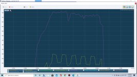
This all leads to another question - if I'm pulling 675 amps at 52 volts but am only seeing a max of 33,000 - what does that mean? Is duty cycle low and motor current insanely high? (MGM controllers don't log duty cycle, and I'm not sure if the current reading is motor current or battery current)
This all leads to another question - if I'm pulling 675 amps at 52 volts but am only seeing a max of 33,000 - what does that mean? Is duty cycle low and motor current insanely high? (MGM controllers don't log duty cycle, and I'm not sure if the current reading is motor current or battery current)
WB projects
Active member
No. I'm talking about the current being drawn from the battery vs the current pulses going to the motor. VESC and APD both show it in their logs; MGM doesn't. Let me give you an example - if you're motor's running at 50% duty cycle, then power is only going to the motor half the time. So the current draw on the battery is half as much (well, a little more than half because of inefficiencies; but basically half). In other words, if the ESC is only feeding the motor 50% duty cycle, but when it is sending power to the motor, those pulses are 200 amps, then it'll draw 100 amps from the battery. As duty cycle approaches 100%, battery current gets close (and starts to match) motor current.
I may not be explaining it well; it's actually pretty straight forward.
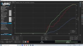
Here's a VESC screenshot of battery current, motor current and duty cycle:

Don't look at the peak numbers; the VESC gets flaky up there. Look at 50% duty cycle. At 50% duty cycle, motor current is almost exactly 200 amps, and battery current is a bit under 100 amps. Of course in the real world, nothing's perfect, but this is a pretty good example.
I may not be explaining it well; it's actually pretty straight forward.
Here's a VESC screenshot of battery current, motor current and duty cycle:

Don't look at the peak numbers; the VESC gets flaky up there. Look at 50% duty cycle. At 50% duty cycle, motor current is almost exactly 200 amps, and battery current is a bit under 100 amps. Of course in the real world, nothing's perfect, but this is a pretty good example.
Don't think of duty cycle as being related to current. If youre battery could put out infinite current, you would put something like 10,000+ amps into the motor at 100% duty at low rpm. A controller (unless it doesnt actually have current sensor on the phases) should put the same phase current into the motor as programmed from 0 rpm all the way to where back EMF matches battery voltage.
motor current = torque
voltage = rpm
duty cycle = % of total power of the combination (how much the battery can put out in combination with as much current as the motor's inductance allows in the allotted time)
motor current = torque
voltage = rpm
duty cycle = % of total power of the combination (how much the battery can put out in combination with as much current as the motor's inductance allows in the allotted time)
Last edited:
^ I think that's a good way to look at it. What we care about is total power in the system (without becoming wildly inefficient anyway) - that's watts. Duty cycle is an element that lets you get to maximum power in the system. For example, I was running into problems with the VESC setup and hitting only about 60% duty cycle - running more voltage would've helped. But that would've also required more torque, and that means more current - eventually I'd exceed the ESC current capacity or the motor's current capacity.
The only part I disagree with is "If youre battery could put out infinite current, you would put something like 10,000+ amps into the motor at 100% duty at low rpm." I think that's not accurate because back EMF and inductance play a role in maximum current that can be applied to a motor. And at low rpm, you're seeing fairly low current because the duty cycle is short, and the motor inductance limits the current from peaking infinitely (again, due to short duty cycle). Correct me if I'm wrong.
And as an aside, writing this is allowing me to procrastinate pulling the engine out of the car. I unbolted the headers last night; and there are few things on earth more painful than unbolting (or bolting) small block ford headers; especially while trying to shoot a timelapse at the same time.
If you know the math below, ignore me, but Im sure others can learn:
I dont know the resistence of the 30100, but as a guess, Id say probably ~.005 ohm (probably too high for a 5 turn motor that has that much copper in it). Also, slotless motors have REALLY low inductance, which Id bet most cheap ESCs blow up trying to run them. Id guess the 30100 probably has around 15 uH. With 63 volts, max current (I=V/R), current would top out at 12,600 amps. With 15 microhenries of inductance (again, its a guess), the time constant is 3 milliseconds (T=L/R). That means 63% of 12,600 amps will be flowing in just 3 milliseconds. At 8khz pwm frequency (if you commanded 100% duty cycle), you would be at ~515 amps by the end of the first cycle!
I read some documentation on the MGM
controllers. I think the default is 8khz, and the minimum pulse width is 5%. With the above guesses, the minimum pulse for your controller is about 27 amps at those settings.
The above is JUST the first pulse. That doesn't include any stored current from any previous pulses.
Last edited:

